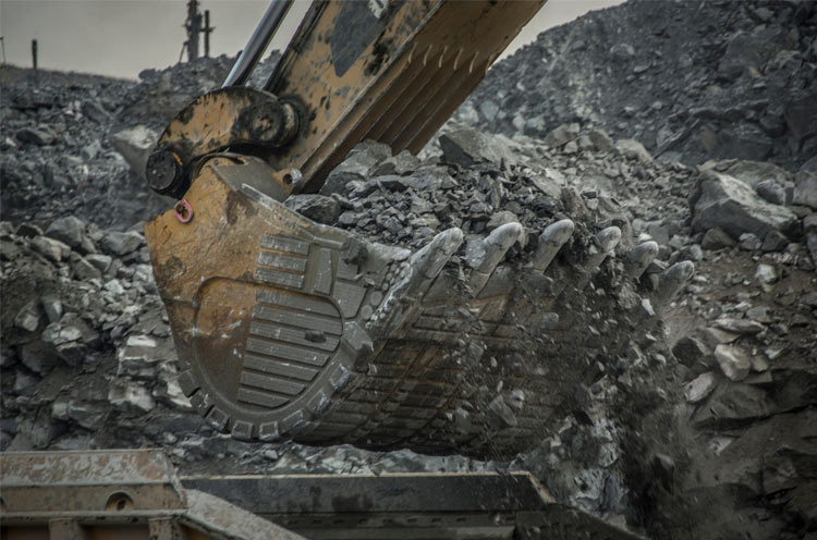
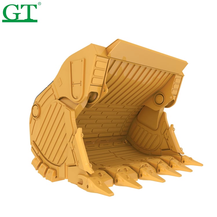
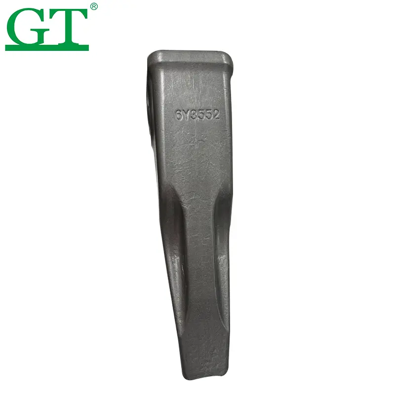
הדלי לסלע עבור המחרשה ההידראולית 6040 נבנה במיוחד במטרה למקסם את תפוקת העבודה בסביבות כרייה קשות ביותר. הדלי בנוי למשיכות, יעילות וטיפול מדויק בחומרים, ומבטיח הפסקות מינימליות וניהול עומס אופטימלי בעבודה עם חומרים קשיחים וחומציים כמו גרניט, קוורציט ותרכות ברזל.
1. תכונות דלי סלע
בניית מטען כבד
מeger עם פלדת סגולה בעלת חוזק גבוה ומרכיבים עמידים במיוחד בפני בלאי כדי לעמוד במכות קשות ובלחיצה.
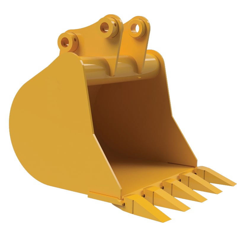
גאומטריה מותאמת של הדלי
בנה למילוי מהיר ושחרור קל של החומר כדי לשפר את זמני המחזור ולחסוך בצריכת דלק.
חלקי בלאי ניתן להחלפה
מלווה בחלקים הניתנים להחלפה (GET - Ground Engaging Tools) כמו אדapters, שיניים וtablות בלאי, כדי להאריך את חיי הדלי ולמזער את זמני השבתה לתיקון ותחזוק.
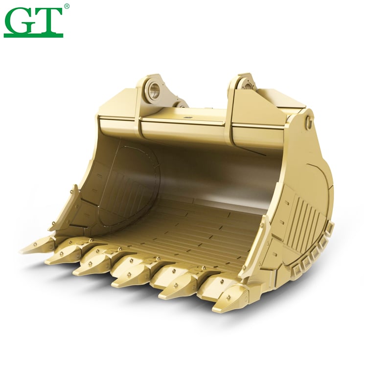
קיבולת גבוהה
הנפח הסטנדרטי נע בין 14.0 ל-16.5 מטר מעוקב (18.3 עד 21.6 יארד מעוקב), עם גדלים מותאמים אישית לפי הבקשה.
מרכיבים מוגזים ויוצ casting
מ 결יב רכיבי פליזות ב_zones מתח גבוה עם בירוטי ברגים רובוטיים כדי להבטיח שלמות מבנית
ב. חלקים ל baldar
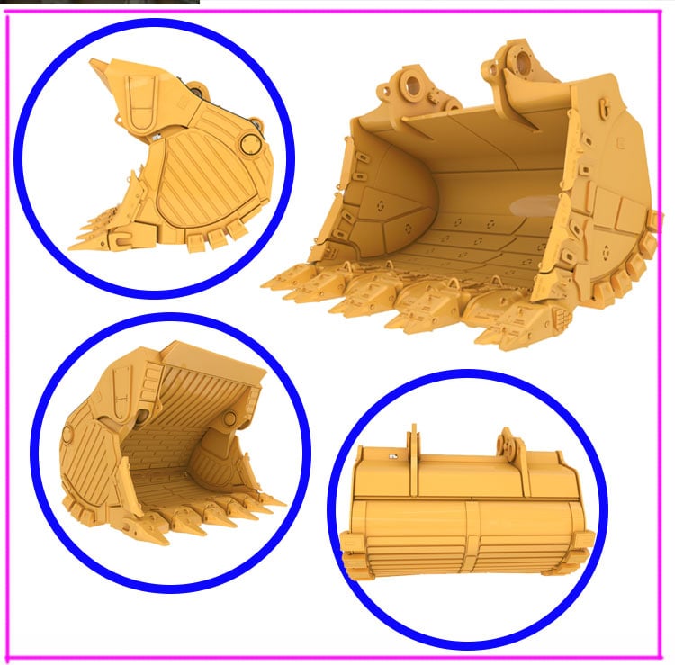
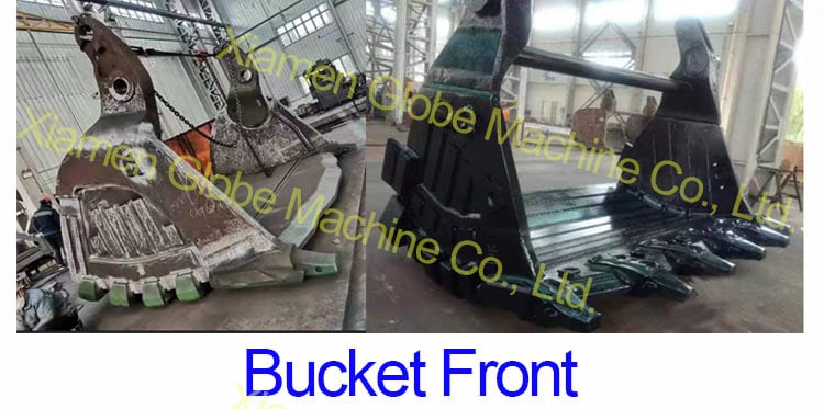
1. חזית baldar (או פני baldar)
🔹 פונקציה:
חזית baldar היא המשטח המוביל שנוגע ראשון בקרקע או בחומר. הוא אחראי על תחילת הפעולה של חיתוך, שבירת או איסוף, והוא נתון להשפעה של מ удар ובליטות.
🔹 תכונות מבניות:
בדרך כלל מעוקם או משופע כדי ל אופטמל זרימת חומרים
מוגז עם לוחות בלה או רכיבי חיכוך
משלב בצורה צמודה עם שן הקצה ומערכת השיניים
🔹 חומרים נפוצים:
פלדות עמידות בעומס ובעיטות (למשל, Hardox 450/500).
יש להחיל קשיחות משטחית ו הגנה מפני בליה.
🔹 מונחים:
חזית הדלי – מונח כללי.
פני הדלי – משמש כאשר רוצים להדגיש את משטח העבודה.
בעיצוב המפורט, עשוי לכלול את אזור ריסוק השיניים.
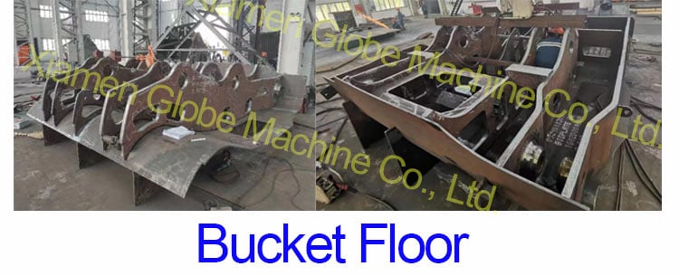
2. תחתית הדלי (או ריצפת הדלי)
🔹 פונקציה:
תחתית הדלי נושאת את רוב החומר במהלך הפעולה, וכן מتحملת עומסים סטטיים ודינמיים. זהו אחד המשטחים המובלים ביותר עקב זרימת החומר המתמדת וההשפעות.
🔹 תכונות מבניות:
משטח פנימי שטוח או קמור במעט.
לרוב כולל סריגים לחיזוק ופסי ביטחון נגד בלאי.
מחוברת בלחימה ללוחות הצד ולשפת החיתוך.
🔹 חומרים נפוצים:
לוחות פלדה בעלי עמידות גבוהה בפני בלאי (למשל NM500, Hardox).
עשוי להכיל לוחות בלאי המותקנים באמצעות ברגים או לحام.
🔹 מונחים:
רצפת הדלי – מונח טכני יותר לשימוש בשרטוטים.
תחתית הדלי – נפוץ בשימוש בשטח.
רכיבים קשורים: לוחות בלאי, מוטות בלאי, לוחות תapus.
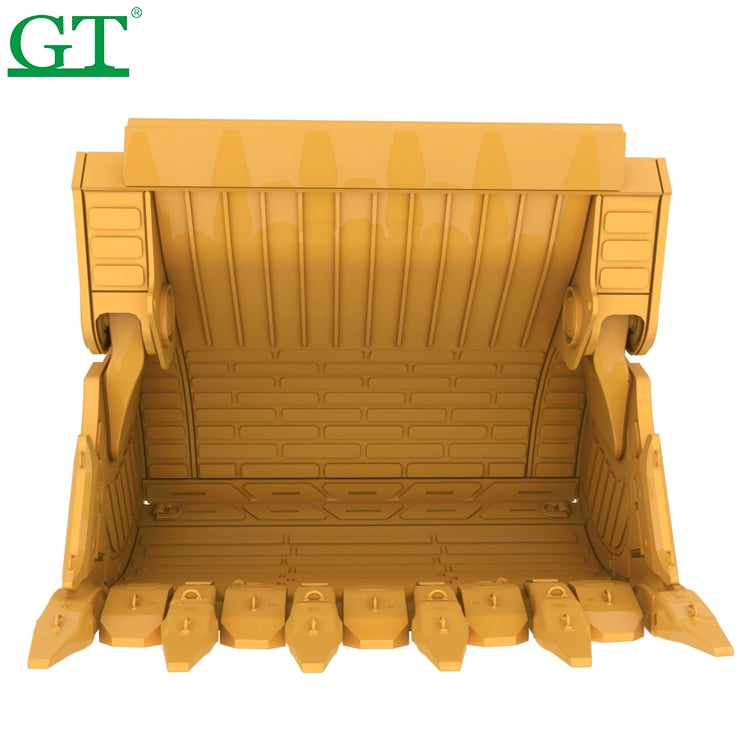
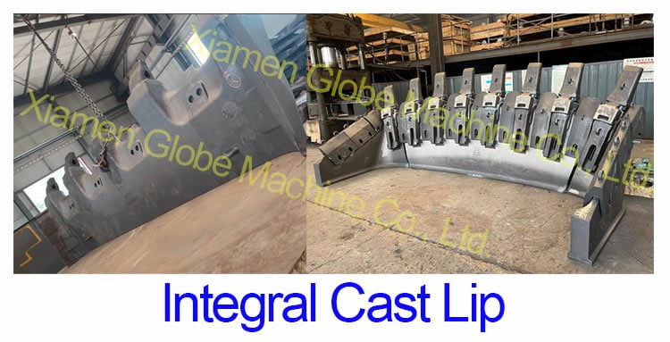
3. שפה יצוקה אינטגרלית
🔹 פונקציה:
השפה היצוקה האינטגרלית היא הרכיב העיקרי של הדלי האחראי לחיתוך. היא חודרת אל הקרקע הקשה, סלע או מינרל, וכן תומכת בהתקנת שיני הדלי.
🔹 תכונות מבניות:
שפת ישרה או בצורת V מצוידת במתכתיים להתקנת שיניים.
עשוי להיות רכיב מחליפה שניתן להחליף באמצעות ברגים או לحام.
בדרך כלל מוצעים בחלקים ובמגינים עבור תחזוקה מודולרית.
🔹 חומרים נפוצים:
יציקות פלדה או סגסוגת מנגן גבוהה.
בנויים למשיכה ולעמידות בפני שבירה.
🔹 מונחים:
הקצה החותך – מתייחס ללהט החותך בפועל.
שפת הגילגל – מונח רחב יותר הכולל את כל מבנה התחתון הקדמי שמחזיקה את השיניים.
חלקים קשורים: מותקנים לשיניים, שיניים, מגיני שפה, חלקים.
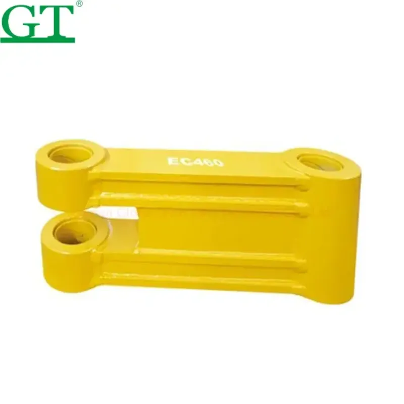
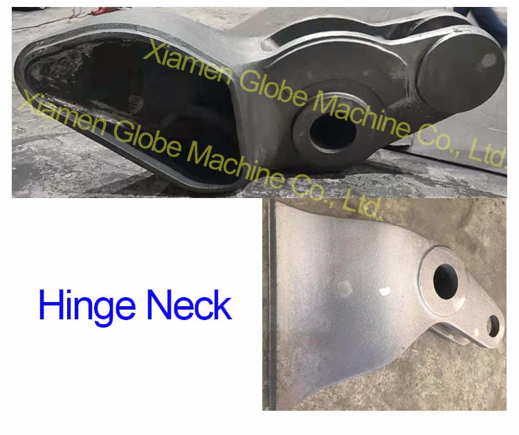
4. צוואר ציר
🔹 פונקציה:
הציר מקשר את הדלי אל זרוע החפרן או הלודר. הוא מאפשר תנועה סיבובית לצורך חופרת, השטחה ושפיכת חומרים.
🔹 תכונות מבניות:
כולל לוחות אוזן עם חורים שהותאמו בדיוק.
מרוכזים סביב סיבת הציר (או סיבת מרכזית).
איזור נושא עומס כבד אשר חייב לשמור על רווחים צרים.
🔹 חומרים נפוצים:
פליזי פלדה לתומכים ולחצינים.
פאות מקשה ושימון מפרקים כדי להפחית בלאי.
🔹 מונחים:
מפרק – מתייחס למערכת המפרק המלאה.
צינור מפרק – הציר המאפשר תנועה.
נקודת סיבוב – ציר הסיבוב.
מונחים נוספים: לוחות אוזן, חצינים, צינורות תומכים.
שלושה נקודות בדיקה עיקריות ל baldachim של מחרשה חשמלית
1.בדוק אם יש התנגשות בין המפרקים ולשוחות החורץ.
2.ודא התאמה בין לוח העקב ללוח הבסיס.
3.בדוק אם יש התנגשות פוטנציאלית בין חבילות הבلى של הלוחות הקדמיים והאחוריים.
4.העבר בזהירות את המכל הפתוח והסגור לאורך טווח התנועה המלא מספר פעמים כדי לבדוק אם יש רעשים חריגים או התנגשויות.
5.הזז את המכל כולו לאט בזמן שהוא מותקן על הזרוע כדי לוודא שהלוח התחתון של המכל נוגע נכון במיקום המעצור המוגדר על הזרוע.
6.אם המעצורים המכאניקליים אינם נוגעים בו-זמנית בשני הצדדים של המכל והזרוע, יש לשנות את המעצורים במכל או בזרוע כדי להשיג מגע דו-צדדי.
7.אחרי שהמכל הקדמי מותקן על הלוח הבסיסי:
8.הרף ו הסר את תומכי ההפצה.
9.הסר את הלולאות להרמה מהצד הקדמי של המכל.
10.בצע את הליך החימום הקדם-מתאים, וכשתהליך הלحام יסתיים, גלף את בתי החזות לסיום חלק.